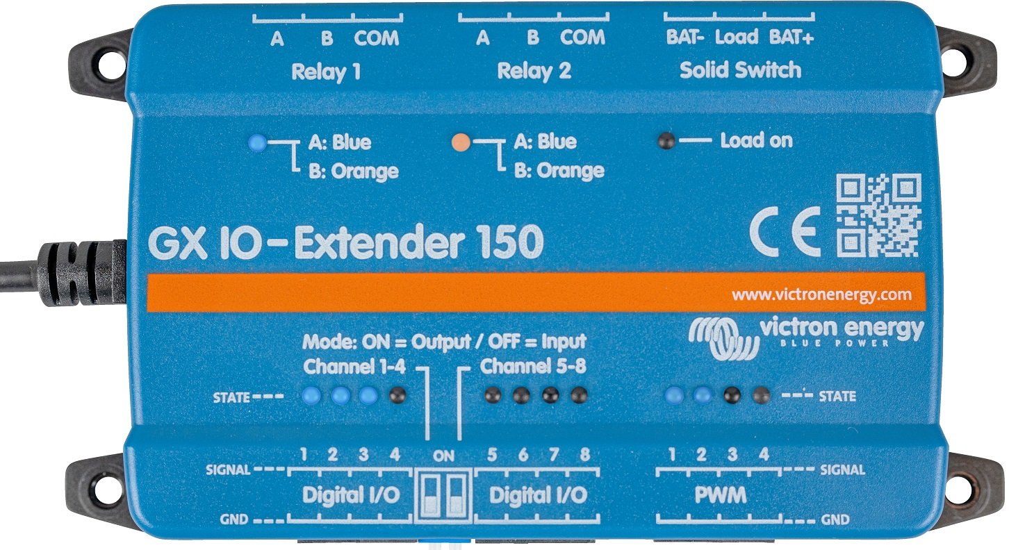
Victron GX IO-Extender 150

Available for backorder

Original price was: €160.93.Current price is: €136.79.

Victron GX IO-Extender 150 – We'd be happy to provide you with more information about this product. Please contact us.

BPP900800150

Available for backorder

Victron GX IO-Extender 150

Victron GX IO-Extender 150 The GX IO-Extender 150 is an expansion module that increases the inputs and outputs of a GX device such as the Cerbo GX or Ekrano GX. The module connects and is powered via USB and offers eight digital I/Os, four PWM outputs, two latching relays, and a solid switch. Control is managed via Node-RED on the GX device and via the Switch panel in the user interface, locally or remotely via VRM. Multiple modules can be connected to a single GX device. Applications If you are reaching the limits of your GX device's inputs and relays, this is a significantly more compact and cost-effective solution than installing a second GX device. Dimming lights, switching pumps, reading alarm contacts, or operating a powerful contactor coil: it all happens from a single module with spring clips. And because everything is available in Node-RED, you build automations around it without additional hardware. * Marine and camper: reading bilge, smoke, and burglar alarms, dimming lighting * ESS and off-grid: switching DC loads and controlling contactors * Systems where the digital inputs or relays of the GX device are depleted * Node-RED installations with their own automation logic Digital inputs and outputs Eight digital I/Os, galvanically isolated from USB and equipped with LED status indication. The ports are divided into two groups of four, each configurable as an input or output using DIP switches: eight inputs, eight outputs, or four in and four out. A power cycle is required after changing the setting. Note: the digital outputs are intended for signaling and supply a maximum of 4 mA — they are not suitable for switching loads directly. The ports can withstand a maximum of 5.5 V; higher voltage will cause permanent damage. PWM Outputs Four PWM channels with LED status indication, voltage level 5 V, and a resolution of 8 bits at 1.5625 kHz. Suitable for applications such as LED dimming and motor speed control. Relays and Solid Switch Two potential-free latching relays (bistable) that maintain their position in the event of power failure, with LED indication. Additionally, a solid switch for switching DC loads — resistive, capacitive, or inductive, for example, the coil of a heavy-duty contactor. The solid switch can also be configured as a momentary switch. Connection and Mounting Connection via USB to the GX device; this connection also provides the power supply. On some Cerbo GX versions, the USB port next to the HDMI connection is not suitable for this purpose — consult the GX device manual. All connections are designed as pluggable spring terminals. Mounting on a wall or, with the separately available DIN35 adapter, on a DIN rail. Software The module is fully supported in Venus OS with Node-RED; the Large firmware image is required for this. The ready-to-use Switch and Switch control nodes are included in the supplied node-red-contrib-victron package. Digital outputs and relays can also be controlled without Node-RED via the Switch panel on the GX device screen or via VRM. Documentation * GX IO-Extender 150 Manual (EN, HTML5) (https://www.victronenergy.com/media/pg/GX_IO-Extender_150/en/index-en.html) * GX IO-Extender 150 Manual (EN, PDF) (https://www.victronenergy.com/upload/documents/GX_IO-Extender_150/203216-GX_IO-Extender_150-pdf-en.pdf) * GX IO-Extender 150 Datasheet (EN, PDF) (https://www.victronenergy.com/upload/documents/Datasheet-GX-IO-Extender-150-EN-.pdf) * Dimensioning Drawing (PDF) (https://www.victronenergy.com/upload/documents/DimensionDrawing-GX-IO-Extender-150.pdf) * 3D Dimensioning (PDF) (https://www.victronenergy.com/upload/documents/DimensionDrawing-GX-IO-Extender-150-3D.pdf) * 3D Model (STEP) (https://www.victronenergy.com/upload/documents/DimensionDrawing-GX-IO-Extender-150-3D.STEP) * Venus OS Large and Node-RED – Installation Documentation (EN) (https://www.victronenergy.com/live/venus-os:large) * Victron Energy ISO 9001 Certificate (PDF) (https://www.victronenergy.com/upload/documents/ISO9001-certificate-2024-EN.pdf) Victron Energy does not publish Dutch-language documentation for this article; the manual, datasheet, and drawings are in English. Contact Would you like to know how many inputs and outputs your installation requires, or how to set up the control in Node-RED? Our specialists are happy to assist you with system design and automation. Please contact us (https://www.top.systems/nl/contact/). Specifications Application Expansion of inputs and outputs of a GX device Power supply Via USB Power consumption < 100 mW idle, max. 1 W (< 200 mA at 5 V) Digital I/O 8 units, isolated from USB, configurable as 8 in, 8 out or 4 in + 4 out Digital I/O levels Inputs 3.8 – 5.5 V; outputs 5 V, max. 4 mA PWM outputs 4 channels, isolated from USB, 5 V, 8 bits at 1.5625 kHz Relays 2x latching (bistable), potential-free Relay contact load DC 3 A at 30 V | 1 A at 60 V | 0.3 A at 220 V (max. 90 W) Contact load relay AC 2 A at 60 V | 1 A at 125 V | 0.5 A at 250 V (max. 125 VA) Solid switch For resistive, capacitive, and inductive DC loads Connections Plug-in spring terminals Mounting Wall or DIN rail (with adapter accessory) Manufacturer Victron Energy Warranty 5 years We would be happy to provide you with more information about this product. Please contact us contact join us.
an electric sloop? See our full range.